S2000 Alignment
By Rob Robinette
After installing a front bump steer kit and roll center adjusters I knew the front toe would be way out of spec. Instead of spending $140 for a full alignment I knew I could adjust the front toe pretty easily. Changing the front toe is straightforward because changing it doesn't really affect camber or caster. The rear is a different story--change the toe and the camber will change too.
If you don't want to do this yourself make sure your alignment shop is willing to set your desired alignment specs. Many shops will not set anything outside the factory specs for liability reasons. If you simply tell them to "set the maximum negative camber" they may set the maximum allowed by the factory specs and you'll be out close to $200 for a low performance alignment. Keep in mind that many alignment techs don't really understand what the alignment adjusters do or how to move the suspension for more negative camber--they simply look at the alignment machine screen and turn the adjuster bolts until they get something acceptable. The best possible situation is a shop that will let you get under the car with them and show them how to move the adjusters for maximum camber and caster.
Other Alignment Related Pages: Corner Balance, Front Bump Steer, Convert Toe Angle to Inches, Convert Toe Inches to Degrees, Roll Centers, Adding Camber
Notes on S2000 Alignment
Ride height greatly affects the camber. Lowering a car by 1 inch or more will allow you to set more negative camber than at stock ride height. Changing ride height WILL change camber and toe-in so get your ride height right before you align the car.
Front and rear toe settings must be precisely set because they can greatly affect handling, tire wear and cause an un-centered steering wheel. Camber and caster do not need to be precisely set and variation from left to right side of the car is ok. Many race teams run more negative camber on the tires that will be on the outside of most of a track's corners.
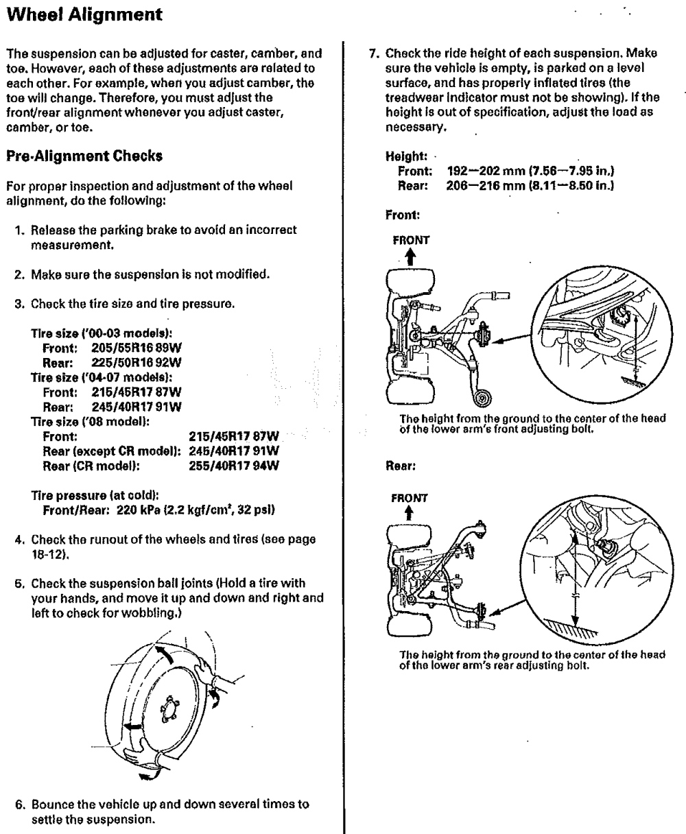
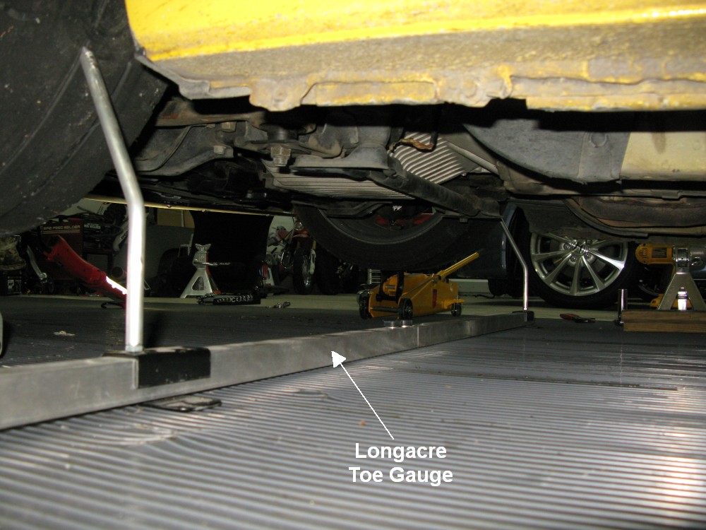
The car's weight must be on the wheels to measure alignment settings. The alignment settings change as the suspension moves up and down so the car needs to have it's weight on the wheels. To make room for the alignment gauge I put the tires up on 4 inch thick wood planks. That gets the car high enough to make positioning the toe gage easier. Another option is to jack the car up, place the toe gauge in place, then lower the car and take the measurement.
Set your normal track tire pressures before the alignment (OEM spec is 32psi cold).
You must have a flat and level surface to accurately measure camber and/or caster. A level surface isn't absolutely necessary for setting the toe.
Work on one end of the car at a time. If your steering wheel is centered you can assume your car's front and rear thrust vectors are aligned. Make changes to one end of the car and then test drive it. If the steering wheel is off-center then the toe is out of whack. Make adjustments if needed to get the steering wheel re-centered, then work on the other end of the car. If you change both the front and rear alignments you won't know which axle is causing the cocked steering wheel (thrust vector).
It's good practice to mark all the alignment adjusters before you begin to move them and after they are set. I use white nail polish to put a stripe across the adjuster and then use a sharp scribe to scratch a reference line in the white polish. If things go to crap you can always go back to the previous settings. Once you get a good, verified alignment you can re-mark the adjusters so you'll know if they slip.
If any alignment adjuster slips it will change the toe setting. It's easy to check the toe with a tape measure--if your toe is still good then the camber and caster are still good too.
All of the alignment adjusters have a lock nut. Hold the adjuster with one wrench while you loosen the lock nut with another. The camber and caster adjusters use a bolt with an eccentric head to cam the adjusters in and out. Don't forget to torque down the lock nuts when finished. You've got to be careful to not move the adjuster as you tighten down the adjusters and you've got to verify the alignment settings after you lock them into place. Reference the Workshop Manual pages above for torque settings for the lock nuts. The latest Workshop Manual says to replace the alignment adjuster lock nuts every time they are loosened. Of course I don't do that but I have to almost double the recommended torque settings on the lock nuts to keep them from slipping on track with R compound tires.
Always have a wrench on both ends of the alignment bolts when loosening or tightening them. That way you will see if the adjuster accidentally moves.
Measuring caster is a pain in the butt because you have to do a steering sweep (caster sweep) after each adjustment so I normally leave it alone and just adjust the camber and toe.
If you're going to change the caster then start with the caster, then reset the toe, then set the camber you want and finish up with the final toe adjustment.
Remember, any camber or caster adjustment, front or rear, requires a toe adjustment too.
Recommended Reading
Alignment Specs
Alignment specs come in several flavors. There's degrees-minutes which Honda uses to specify caster and camber but some manufacturers and shops specify them in much easier to understand decimal degrees. Then there's toe that can be given in inches, which Honda uses, but it can also be specified in millimeters, degrees-minutes or decimal degrees. In the listing below I give all the equivalent specs.
Degrees-minutes is probably the strangest specification but just keep in mind there are 60 minutes in 1 degree, so the rear camber setting of -1º 30' (minus 1 degree, 30 minutes) is equal to -1.5 decimal degrees or -1 1/2 degrees.
OEM Caster, Camber & Front Toe-In for All Years
Caster 6º +/- 15' (6 degrees plus or minus 15 minutes) or the range of 5º 45' to 6º 15'
Decimal degrees: 6º +/- 0.25º (6 degrees plus or minus 0.25 degree) or the range of 5.75º to 6.25º
Maximum difference between left and right side 0º 10' (0.167º decimal degrees)
Camber Front -0º 30' +/- 10' or the range of -0º 20' to -0º 40' degrees & minutes
Decimal degrees: -0.5º +/- 0.167º or the range of -0.333º to -0.667º
Maximum difference between left and right side 0º 10' (0.167º decimal degrees)
Camber Rear -1º 30' +/- 10' or the range of -1º 20' to -1º 40' degrees & minutes
Decimal degrees: -1.5º +/- 0.167 or the range of -1.333º to -1.667º
There is no max difference between left and right side given but 0º 10' is recommended
Front Total Toe-In Inches: 0 +/- 0.08 inch, Millimeters: 0 +/- 2mm
Degrees Minutes: 0º +/- 0º 11', Decimal Degrees: 0º +/- 0.19º
AP1 (2000 - 2003) OEM Rear Toe-In Specs
Inches: Total Toe-In is 0.24 inch +/- .08 inch or the range of 0.16 - 0.32 inch
For each rear tire toe-in is 0.12 inch +/- 0.04 inch or the range of 0.08 to 0.16 inch
Degrees-Minutes: Total Toe-in is 0º 33' or the range of 0º 22' to 0º 44'
For each rear tire toe-in is 0º 17' or the range of 0º 11' to 0º 22'
Decimal Degrees: Total Toe-In is 0.56º or the range of or 0.37º to 0.75º degrees
For each rear tire toe-in is 0.28º or the range of 0.19º to 0.37º degrees
Millimeters: Total Toe-In is 6mm +/- 2 or the range of 4 to 8mm
For each rear tire toe-in is 3mm +/- 1 or the range of 2 to 4mm
AP2 (2004 and newer except CR) OEM Rear Toe-In Specs
Inches: Total Toe-In is 0.14 inch +/- 0.08 inch or the range of 0.06 to 0.22 inch
For each rear tire toe-in is 0.07 inch +/- 0.04 inch or the range of 0.03 to 0.11 inch
Degrees-Minutes: Total Toe-in is 0º 20' or the range of 0º 8' to 0º 31'
For each rear tire toe-in is 0º 10' or the range of 0º 4' to 0º 16'
Decimal Degrees: Total Toe-In is 0.33º or the range of or 0.14º to 0.51º degrees
For each rear tire toe-in is 0.16º or the range of 0.07º to 0.26º degrees
Millimeters: Total Toe-In is 3.7mm +/- 2 or the range of 1.7 to 5.7mm
For each rear tire toe-in is 1.8mm +/- 1 or the range of 0.8 to 2.8mm
CR OEM Rear Toe-In Specs
Inches: Total Toe-In is 0.22 inch +/- 0.08 inch or the range of 0.14 to 0.30 inch
For each rear tire toe-in is 0.11 inch +/- 0.04 inch or the range of 0.07 to 0.15 inch
Degrees-Minutes: Total Toe-in is 0º 31' or the range of 0º 20' to 0º 42'
For each rear tire toe-in is 0º 15' or the range of 0º 10' to 0º 21'
Decimal Degrees: Total Toe-In is 0.51º or the range of or 0.32º to 0.70º degrees
For each rear tire toe-in is 0.26º or the range of 0.16º to 0.35º degrees
Millimeters: Total Toe-In is 5.5mm +/- 2 or the range of 3.5 to 7.5mm
For each rear tire toe-in is 2.8mm +/- 1 or the range of 1.8 to 3.8mm
The Infamous "UK" Alignment Specs
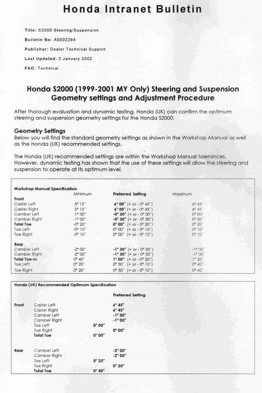
UK Specs (AP1 only)
Front Caster 6º 45' (+ 0.75º over US Spec)
Front Camber -1º (+ 0.5º)
Front Total Toe 0º (no change)
Rear Camber -2º (+ 0.5º)
Rear Total Toe-in 0º 40' (+ 0.036 inch)
The UK Spec is a good moderate alignment for an autocross or track S2000. Toe specs on this sheet are in degrees-minutes (not inches), 0º 20' (0 degrees, 20 minutes) = 0.333º = 0.143 inch toe-in per rear wheel. The UK Spec of 0º 40' TOTAL rear toe-in is equal to 0.286 inch or 0.666º total toe-in. The UK Spec is an AP1 spec so if you want to run the UK Spec on an AP2 I recommend using no more than 0.22 inch of rear toe-in as this is the maximum OEM spec range. The UK Spec should work well with the CR since it's toe specs are so close to the AP1. Note: This bulletin incorrectly shows the Workshop Manual spec rear toe as 1 degree total toe-in which is wrong (1 degree = 0.43 inch), the actual spec is 0.24 inch (0.56 degree or 0º 33') total rear toe-in.
Aggressive Alignment with Stock Adjusters
These setting will typically give you the maximum performance for autocross and track using only the stock alignment adjusters (no camber adding mods) but tire wear will increase on the inside shoulder of the tires possibly shortening their life.
Set the front camber and caster adjusters to max outward extension (move the bottom of the wheel hub outward). Then tweak the adjusters on the wheel with the most caster and camber to match the other wheel. Once the caster and camber are equal on both wheels adjust the toe. Doing this will give you the optimal setting of front camber and caster.
In the rear start with both alignment adjusters set for maximum outward extension (move the bottom of the wheel hub outward). Tweak the wheel with the most negative camber to set the camber equal on both rear tires. Check your toe settings. If you have toe-out or too little toe-in use the toe adjuster to set toe. If you have too much toe-in use the camber adjuster to set the toe. The toe setting is usually the limiting factor so you would normally use the camber adjuster to set the toe.
Aggressive Track Alignment
The S2000 greatly benefits from the addition of a front camber adding device. There are 3 ways to add front camber. Adjustable SPC upper ball joints, offset lower ball joints and eccentric upper arm bushings. All of these will allow you to lean the top of the wheel inward for more negative camber. Check your rules book because eccentric bushings may be a zero point modification.
A standard track alignment is around 6º to 7.5º of front caster, -3.5º front camber, -3º rear camber, zero front toe and 0.24 inch rear total toe-in for the AP1 and 0.14 inch rear total toe-in for the AP2.
Workshop Manual on Alignment
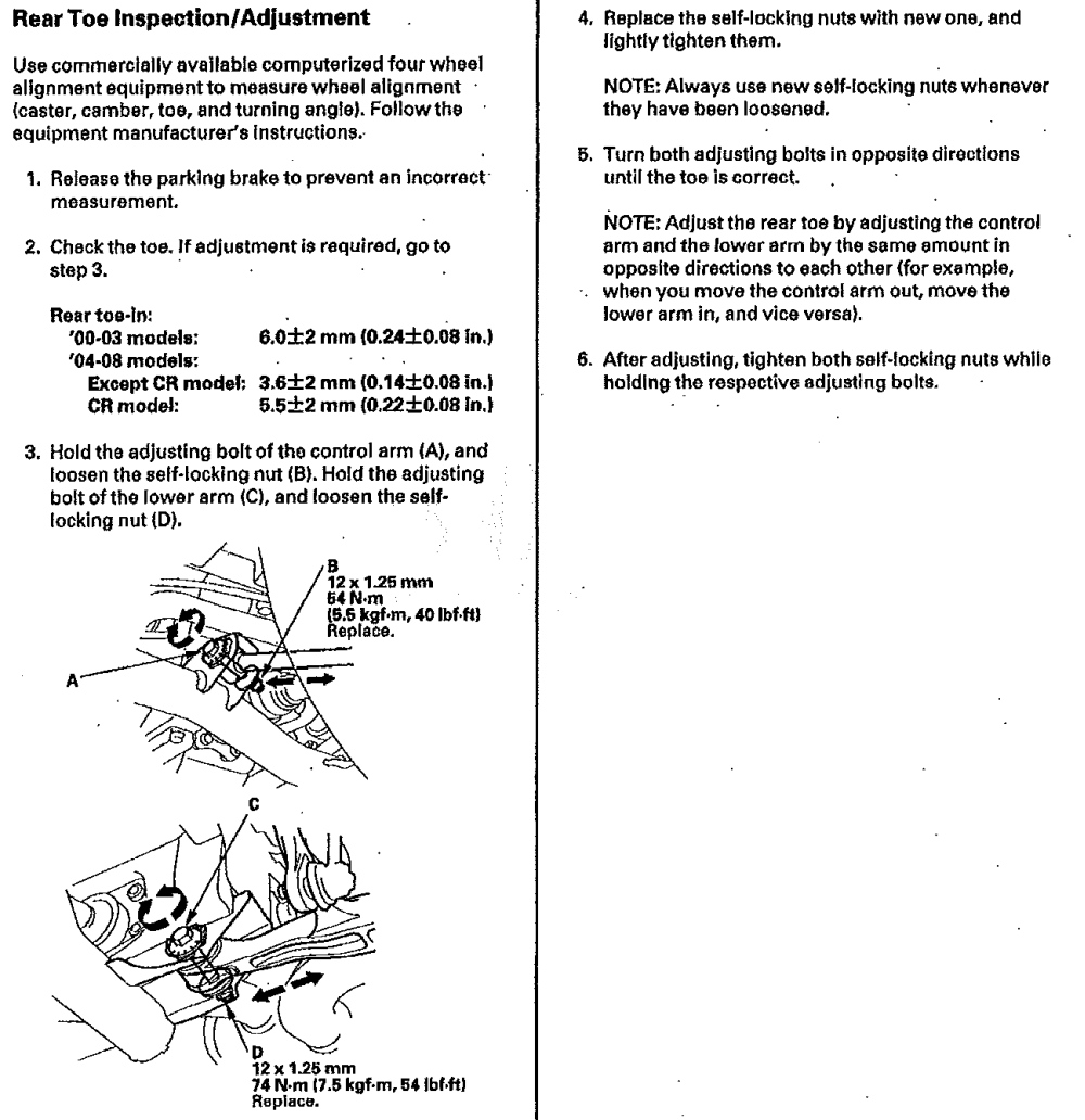
Total Toe-in for All Years
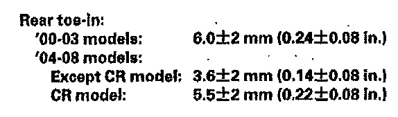
Note the CR has its own toe-in specs.
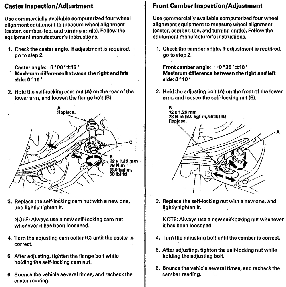
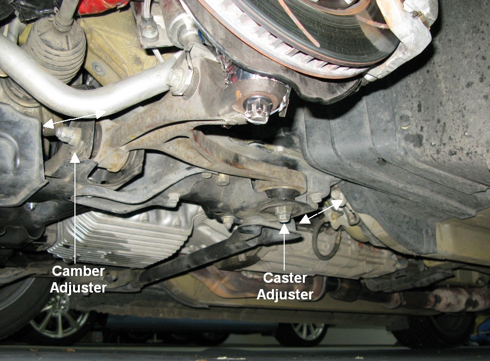
Adjusting Camber & Caster
Camber Adjuster Detail
You can use a camber/caster gauge to measure and adjust your camber and caster.
If you are trying to maximize your camber in the front simply set the camber and caster adjusters to max outward extension (move the bottom of the wheel hub outward). Then tweak the adjusters on the wheel with the most caster and camber to match the other wheel. Once the caster and camber are set adjust the toe. Doing this will give you the optimal setting of camber and caster.
If you are trying to maximize your camber in the rear start with both adjusters set for maximum outward extension (move the bottom of the wheel hub outward). Tweak the wheel with the most negative camber to set the camber equal on both sides. Check your toe settings. If you have toe-out or too little toe-in use the toe adjuster to set toe. If you have too much toe-in use the camber adjuster to set the toe. The toe setting is usually the limiting factor so you would normally use the camber adjuster to set the toe.
Remember, any camber or caster adjustment, front or rear, requires a toe adjustment too.
Measuring Front Camber With SmartCamber Gauge, -3.3 Degrees Set
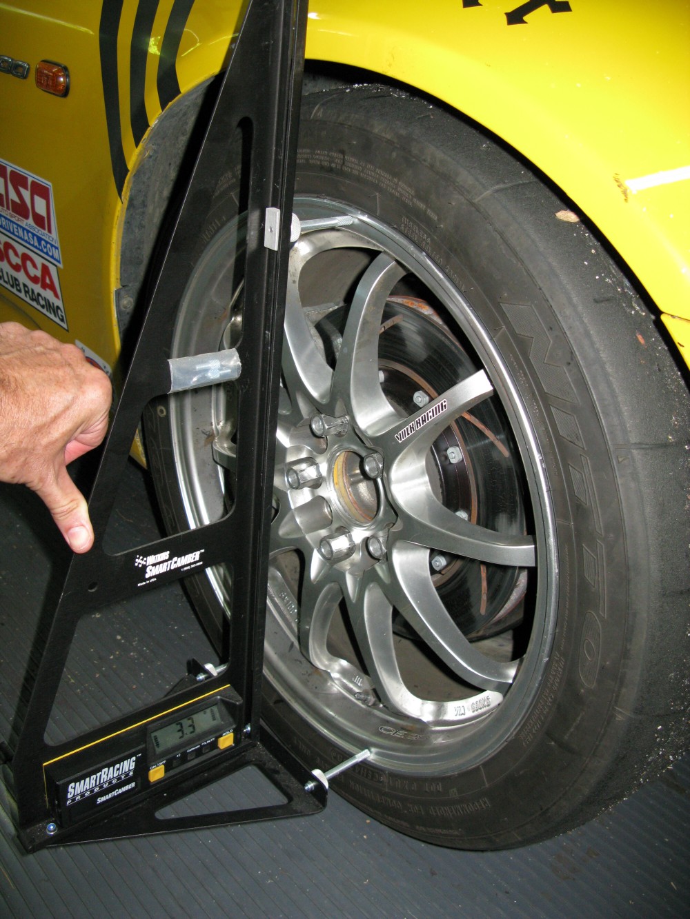
This is what I use to measure camber and caster.
Caster is Kingpin Angle Measurement
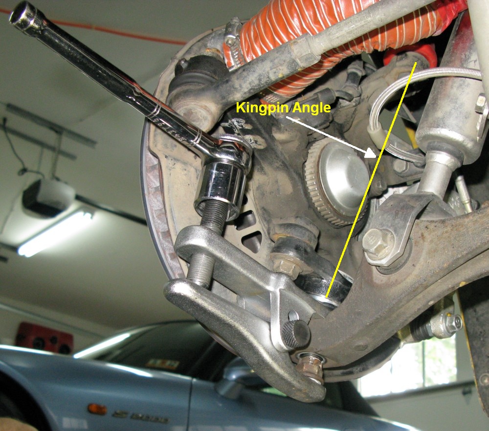
Kingpin angle is the steering pivot between the upper and lower ball joints. The hub and wheel pivot around the kingpin angle when the steering wheel is turned. The more reclined this angle the more caster and the more steering wheel centering force you'll have. More importantly you'll get more camber added into the turn on both wheels as you turn the steering wheel. To measure caster you take a camber reading with the steering wheel centered, then turn the front wheels exactly 20º and take another camber reading. You then plug those readings into a formula to calculate caster. The SmartCamber manual has the directions for using the formula.
If you don't have an absolutely flat and level surface and simply want to add or remove camber you can measure your current camber to get the starting numbers, then add or subtract to set the camber you want.
Example: I measure my current rear camber and get -2.7 degrees left and -3.0 right due to my unlevel garage floor. If I want to reduce the camber by 0.5 degree I would set -2.2 and 2.5. I would then reset my rear toe-in to to spec--any camber change in the front or rear will require a toe adjustment too.
Front Camber and Caster Adjusters
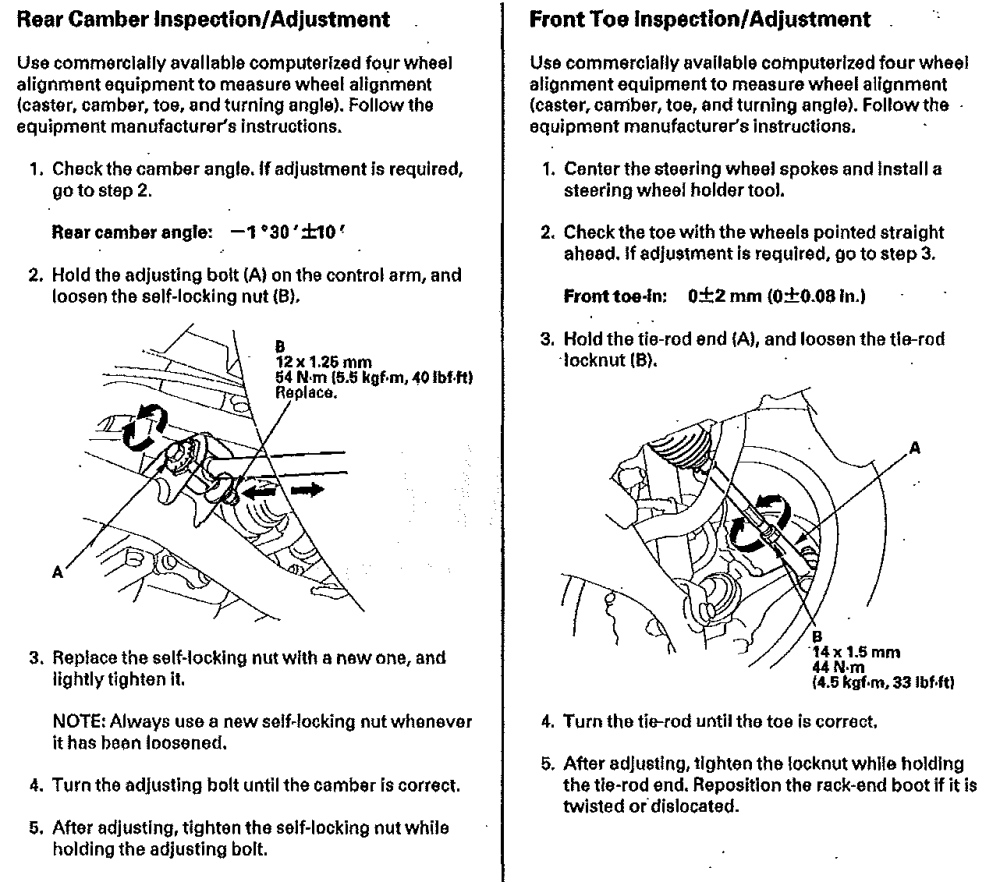
In the rear set camber first then adjust the toe-in (there is no caster in the rear).
Rear Camber and Toe Adjusters
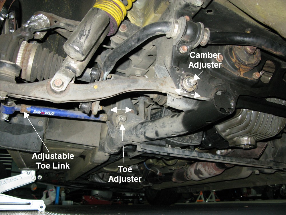
The Adjustable Toe Link is a Megan Racing Bump Steer Correcting Link - It's Adjustable Length Allows Additional Negative Camber Up to -3.0
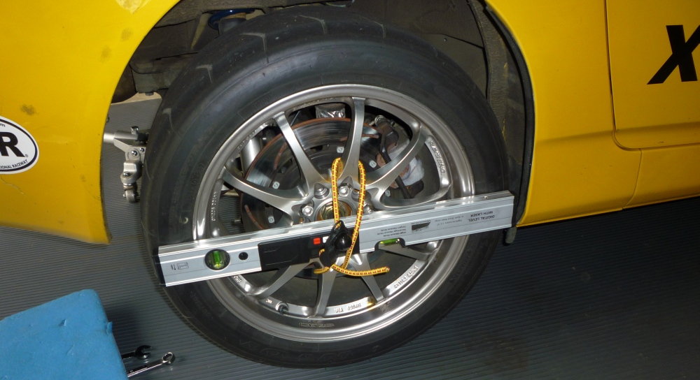
Using a Laser Level to Set Front and Rear Toe
This my preferred method for setting toe front and rear. It's quick, easy and very precise. The first time you do it you have to have a freshly aligned car with known toe settings or you can calibrate your laser level by measuring the laser projection ahead and behind the car. Once calibrated you can use a magnet to hold a metal ruler to the opposite hubs and project the laser dot onto the ruler. You can do this in just a couple of minutes in the pits to verify your toe settings (if your toe settings are still good then you know your camber and caster have not changed).
Inexpensive Torpedo Level Strapped to SmartCamber Gauge
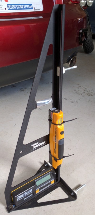
The camber gauge's standoff allow fore accurate placement on the wheel. This is an excellent home alignment tool.
24" Digital Laser Level
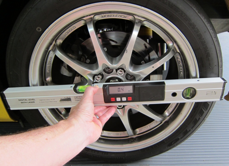
This $55 ebay 24 inch digital laser level can be used to project a laser dot to help set the toe. It projects a laser dot out of one end and also has a digital level display accurate to 1/10 of a degree so it can also be used to set camber and caster. I compared this level to my expensive SmartCamber digital camber gauge and it was within 1/10º.
Checking Camber 90º - 87º = 3.0º negative camber
You can adjust the laser's internal alignment by removing one screw on the end of the level, removing the plastic end cap and adjusting the three hex screws that aim the laser. Simply sight along the length of the level and project the dot onto something about 100 feet away to check the alignment. I also put small rubber bumpers on the backside of the level so they would make contact with the wheel rim lip instead of the tire.
Rubber Bumpers for Wheel Rim Contact
You can use this laser level to quickly and accurately verify front and rear toe settings. If your toe settings are the same as a known good setting then you know the caster and camber settings are the same too because if any alignment adjuster slips it will change the toe--this is true front and rear.
I used the laser level to very accurately set and verify my front and rear toe settings. The easiest way to do this is to start with a known good alignment then take measurements.
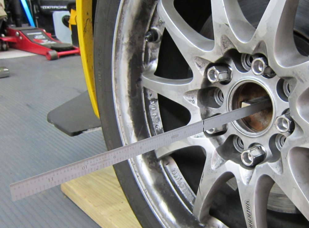
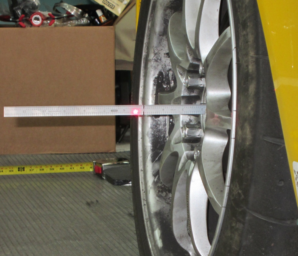
To give your laser an accurate target you can attach a magnet to a 6 or 12 inch steel ruler and place it on the hub center extending outward. I attached a magnet to a 12" precision metal ruler and stuck it to the front hub (you may have to pop your wheel center cap). A 6" ruler will work too. A tape measure can also be used.
Once you get the readings on the hub rulers record them for future reference. You can then verify your alignment settings in about two minutes at the track using the laser level and magnetic ruler.
Magnet Holding Ruler to Hub
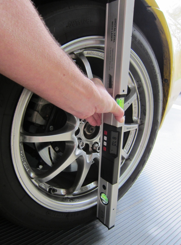
You then place the laser level across the center of the wheel as shown above and shine the laser on the ruler at the front hub. For hands free lasering you can use a bungee cord to hold the laser level to the wheel.
Hands Free Laser for Toe Adjustment
Laser Dot on Ruler
Calibrating the Laser
If you don't want to pay to have the car freshly aligned you can follow this procedure to get your first reference readings. You simply place the laser level against the wheel and project the laser in front and behind the car for a more accurate toe measurement. In my garage I can separate two tape measures by 22 feet, 7 inches (272 inches), one in front of the car and the other behind it. Since the front wheel track is narrower than the rear I had to put the laser level with its narrow edge against the front wheel to get the laser to clear the rear tires and hit the rear target.
Setting 0 toe in the front is easy--the measurement at the front and rear laser targets should be the same. Setting rear toe-in is more involved. I started by converting my desired toe-in in inches to degrees. I used my Convert Toe Inches to Degrees web page and plugged in my desired 0.16 inch total toe-in and 24.6 inch tire diameter to get the equivalent degree for one wheel of 0.186 degree. I then went to my Convert Toe Angle to Toe Inches web page and plugged in the 0.186 degree and 272 inches for the tire diameter (this is the distance between the two tape measures). This gives a total toe of 1.77 inches so that is the measurement difference between the front and rear laser targets I was looking for--0.16 inch of total toe measured on the tire tread is equal to 1.77 inches at the tape measures.
To make things a little easier for me instead of using a tape measure I put inch marks on my 8 foot long level and used it as a laser target. I placed it in front of my car as far forward as my garage space would allow. I put the level on a box to get it up to wheel hub level. I then shot the marked level from all four wheels and noted the readings. I then moved the marked level to the rear of the garage and measured the distance between the front and rear laser targets. For me it was 272 inches. I then took laser measurements at all four wheels. The difference between the measurements taken at the front and back of the garage is the total toe--just like measuring toe on the tire tread itself.
I also took laser readings using a ruler at the opposite wheel hub so I could keep the toe settings equal on both wheels. I then adjusted the rear toe until I got 1.77 inches of difference between the two laser measurements and equal measurements at the opposite wheel hubs.
I took good rear toe readings with the car on the ground then raised just the rear of the car so I could get under it and make adjustments. If you jack the front of the car too the front hubs will move as the front suspension droops. With the front tires on the ground and the rears in the air I took toe readings. My Megan Racing rear bump steer correcting link must be working because at full droop the toe reading didn't change by more than a couple of hundredths of an inch at the front hub. My right rear camber adjuster had slipped a little during my last track day and threw off the toe so I knew its toe was off. I adjusted the right rear camber adjuster to change the toe and match the known good left rear toe. When I put the car down and rolled it back and forth to allow the suspension to unbind I verified the toe-in settings still matched.
Here's how I calculated the correction factor for measuring toe at the opposite hub:
We know 0.24" of total rear toe is equal to 0.06" at the leading edge of the tire (total toe / 4)
The distance from the center of the wheel to the tire edge is 12.3" (24.6" diameter for stock tires)
The S2000's front and rear wheel hubs are 94.5" apart (wheel base)
Therefore you can divide 94.5" by 12.3" to get a Tire to Opposite Hub Correction Factor of 7.683
0.06" measured at the rear tire is equal to: 0.06" x 7.683 = 0.46" measured at each front hub.
If you want to make a 0.05 inch change at the tire tread you would move the laser dot 0.38" (0.05 x 7.683) at the hub.
Measuring toe at the front hub is much, much more precise than trying to use string and measure the difference between the leading and trailing wheel rim lips.
I verified my laser measurements after a shop alignment. With a known setting of 0.16" total rear toe-in (0.08" per rear tire), my laser projected a dot at 4.5" out from the front hubs on the ruler.
Other rear total toe settings are: 0.06" = 4.31" (my personal minimum) and 0.25" = 4.68" (my personal maximum).
For the front wheels 0 toe is equal to 2.1" out from the rear hub on the ruler. This measurement was taken with the laser resting with its thin edge on the wheel so the laser would clear the rear tires.
The laser level's alignment and wheel size and offset will affect this measurement so the these figures only apply to my laser level and CE28 17x9 rear wheels.
Using String to Measure Toe Alignment
A simple and common way to measure toe is to use string. Bent wheels will throw off this method of measuring toe. You can simply spin your wheels and verify there's no wobble at the rim edge. Start by making sure the steering wheel is centered. I used one long piece of twine with rubber bands on each end. I placed one end on a front bumper splitter mount and wrapped it all the way around the car then put the other end's rubber band on the other splitter mount. The string needs to run through the center of the wheels' hub.
Alignment String Around Car
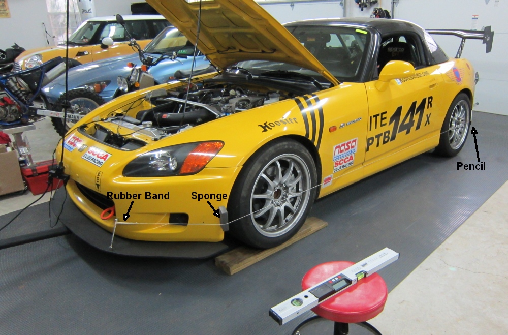
The AP1 S2000's rear end is 2.25" wider than the front (measured at the wheel mating surface) so the string in the front must be moved 1.125" farther off the front wheel to compensate. Don't confuse this measurement with the "Track Width," which Honda says is 1.5 inches wider in the rear. The track width is measured at the outside of the wheel (or tire) so it is affected by wheel offset and backspacing. If your front and rear wheels are different (staggered) you will have to measure the distance from the wheel mating surface to the rim lip to adjust for the wheel difference.
You can use a dry sponge or sanding sponge block on the front bumper to get the extra spacing required by the narrower front (see pic below). Move the sponge on the bumper to get the correct spacing off the front wheel. In the rear place a pencil under the string to get it out away from the tire sidewall then measure from the rim edge to the string. The distance the pencil holds the string off (average of leading & trailing edge off rim) needs to be added to the front 1.125" sponge hold off--if the pencil is holding the string 0.2" of an inch off the wheel lip then the sponge should hold the string 1.325" off (1.125 + 0.2). The downside of using this method to secure the strings is when you roll the car to settle the suspension (which you must do after every adjustment) the pencil will fall out and the string on the rear wheel will move.
With 0 toe the measurement at the front and rear of the rim will be equal. If the measurement at the front of the wheel is larger then there is toe-in. If the measurement at the front of the wheel is smaller it has toe-out.
Pencil Used to Move String Off Rear Tire, Measure to Leading Edge of Wheel Rim
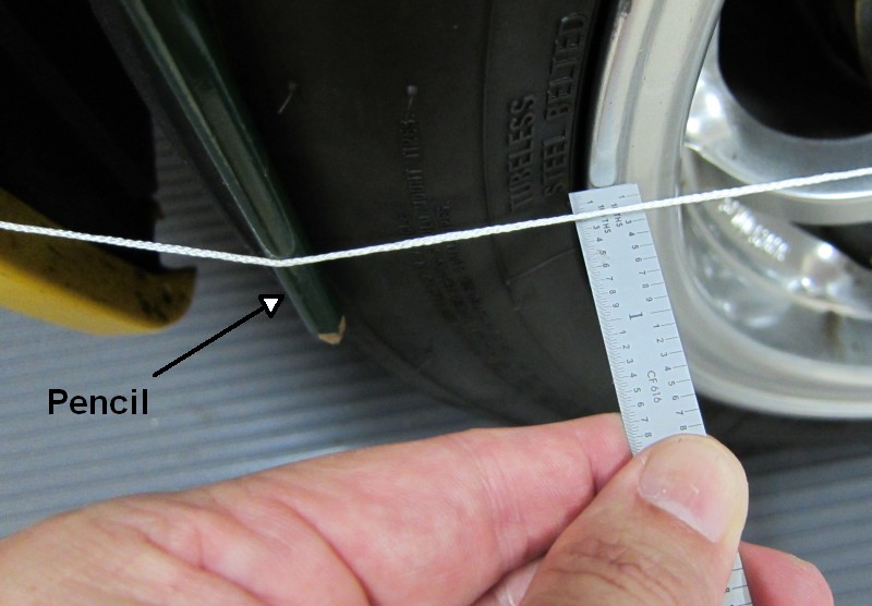
Measure to Trailing Edge of Wheel Rim, Equal Measurement = 0 Toe
This string alignment calculator can do all the math for you. All S2000s' wheelbase are 94.5 inches.
My String Numbers
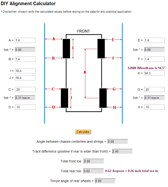
This calculator will do all the string math for you. The toe results from the above string alignment calculator are in degrees, not inches. 0.24" total toe-in is equal to 0.56º total toe-in or 0.28º per rear wheel. For the 2004+ AP2 0.14" total toe-in is equal to 0.33º or 0.16º per rear wheel. The S2000 wheelbase is 94.5 inches. My CE28 17 inch wheels measured 18.4" across the rim lip where string measurements are taken.
Use this calculator to convert toe inches to degrees and this one to convert toe degrees to inches.
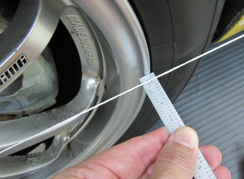
Using a Tire Scribe & Measuring Tape
Another way to measure toe is to use a tire scribe to cut a thin reference line on the tread of your tires, then measure the distance between the lines at the front of the tire and the rear. For 0 toe the distances will be the same. For toe-in the front distance will be shorter. For toe-out the front distance will be longer. For the Honda toe settings given in inches to be accurate you need to measure the toe on the tire at the level of the hub center.
You can even use a tape measure to measure the distance between the two front tires' reference lines. This is why toe measurements are sometimes given in inches while all the other alignment measurements are in degrees.
The Workshop Manual spec for front toe-in is 0 to plus or minus 0.08 inches.
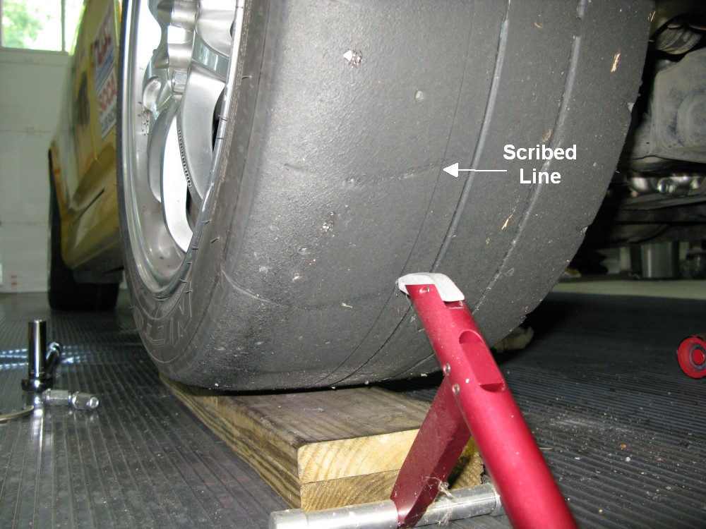
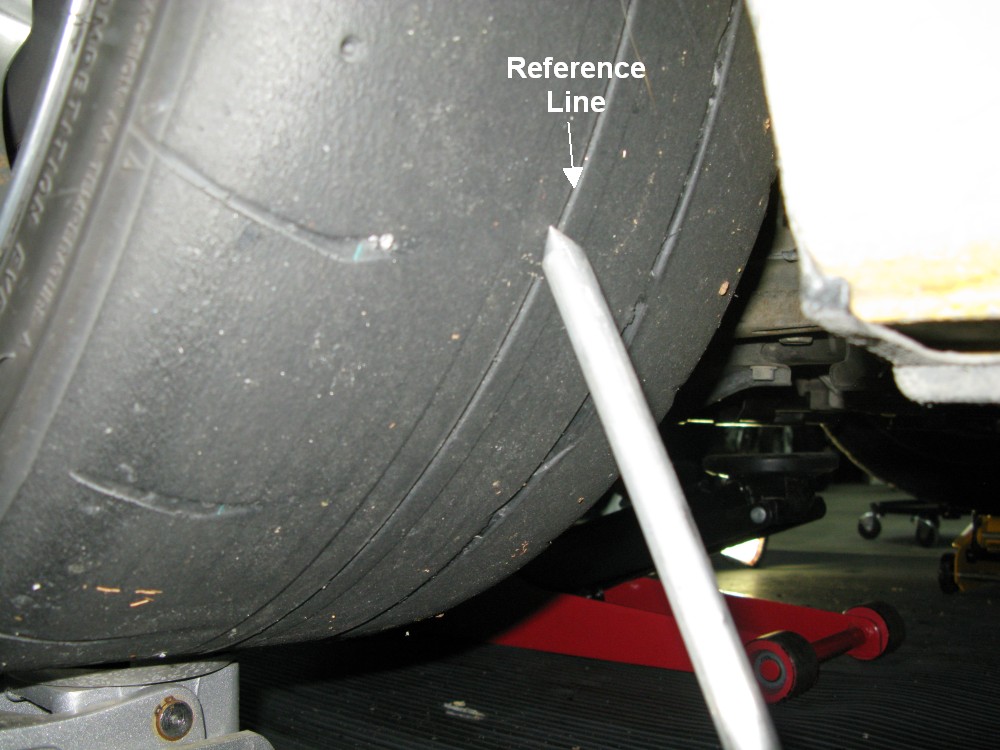
To use a tire scribe you lift the tire off the ground, place the scribe's spring-loaded cutting head against the tire, then spin the tire. The line scribed is "what the pavement sees" as the tire turns, it removes any variation caused by a bent wheel. If your wheels and tires are true and your tires have a straight tread line (like the Nitto NT01s pictured below) you can us the tread line for reference. Putting the scribed line near the outside shoulder of the tire will make it easier to read a tape measure or position the toe gauge.
Using Longacre Tire Scribe to Scribe Adjustment Reference Line
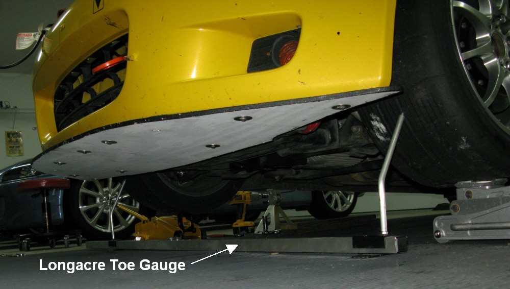
I used a Longacre toe-in gauge to set the front toe to 0. It makes the toe measurement a one man job but a helper really makes this easier.
Ideally you want to measure the toe on the tire at the axle level but this isn't critical if you are just setting the front toe to 0. But the rear toe setting must be measured on the tire at the axle level.
Using Longacre Toe Gauge to Measure Front Side of Tires
Put the Points on the Tires' Scribed Reference Lines
Measuring Back Side of Front Tires
If They Measure the Same as the Front Then Toe = 0
Measuring the Rear of the Tires Shows a Small Amount of Toe-Out
Toe Adjustment
Front and rear toe settings must be precisely set because they can greatly affect handling, tire wear and cause an un-centered steering wheel.
Adjusting Front Toe With a 19mm & 14mm Wrench
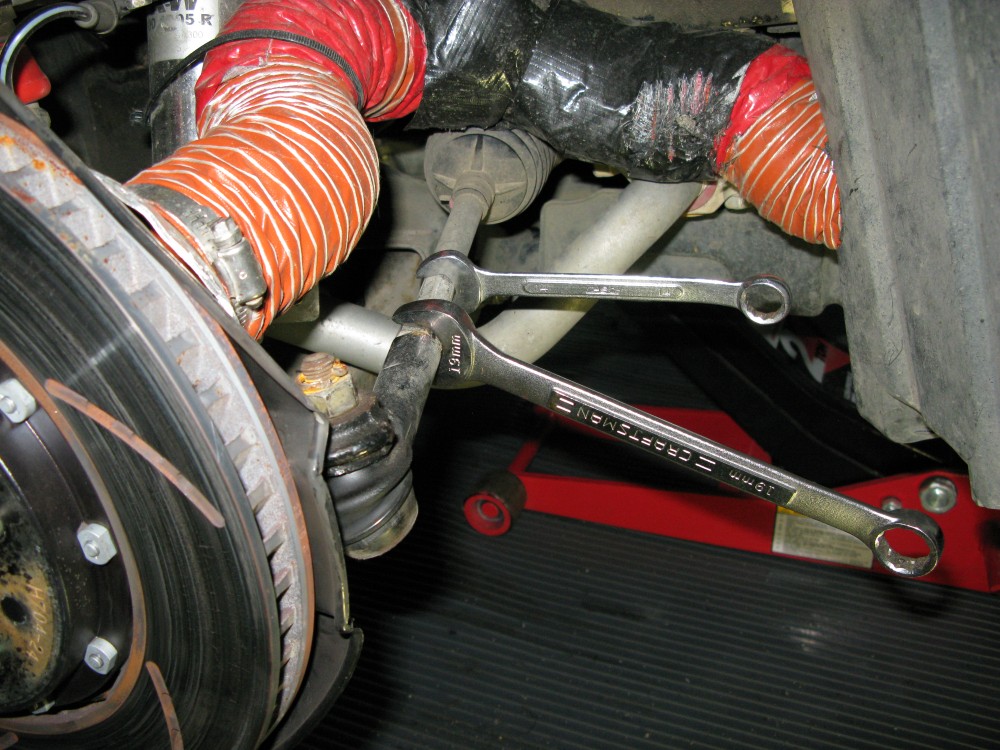
19mm Nut is the Lock Nut, the 14mm Wrench is Used to Turn the Steering Rod to Adjust its Length. Turn the 14mm Wrench Counterclockwise to Shorten the Rod and Add Toe-In, Clockwise to Extend the Rod and Reduce Toe-In.
Both front toe adjusters have normal right-hand threads. I used a Sharpie pen to put a reference mark on the steering rod and rod end. It's good practice to mark all the alignment adjusters before you begin to move them.
Release the 19mm lock nut on the steering rod while holding the rod end with another 19mm wrench (you don't want to apply torque to the rod end ball joint). Use a 14mm wrench to turn the steering rod itself to lengthen or shorten it to change the toe. If you adjust both steering rods the same amount the steering wheel should remain centered.
After my adjustments and a test drive I had to make an adjustment to get the steering wheel back to center. The top of the steering wheel was about 1/2 inch to the right while driving straight. So if I held the wheel centered the car turned left therefore I needed some right toe on both wheels. I lengthened the left steering rod 1/4 turn and shortened the right rod 1/4 turn (this turns both wheels right). I test drove the car and the wheel was centered. I then verified the toe was still set at 0.
When finished don't forget to torque the front toe adjuster lock nuts to 33 lb-ft. You will need two 19mm wrenches to do this. Use one to hold the tie rod end and the other to turn the lock nut. On all the other alignment adjusters I use higher than recommended torque on the lock nuts. I was having trouble with the adjusters moving after running on the track with r-compound tires. I now use about 60 & 70 lb-ft torque on the lock nuts instead of the recommended 40 and 58 lb-ft.
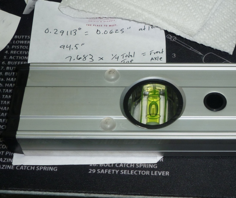
0.25 Inch of Total Toe-In
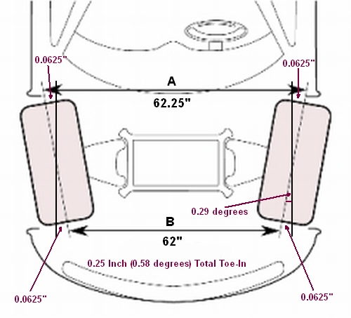
Measurement A - B = 0.25" or 1/4" total toe-in. Note 0.0625" = 1/16"
When measuring toe in degrees you do not need to double the measurement for the leading and trailing edge of the tires as you do when using inches. If one rear wheel measures 0.29º of toe-in and the other measures 0.29º, then total rear toe-in is 0.58º, not 1.16º.
The AP2 (2004+) S2000 has a revised rear suspension and its Rear Total Toe spec was changed to: 3.7mm +/- 2 (0.14 +/- 0.08 inch).
The CR (Club Racer) gets 5.5mm +/- 2 (0.22 +/- 0.08 inch).
Normally toe is measured on the tire tread at the axle level--that's where the Honda 0.25 inch number comes from. If you use the wheel lip to measure toe as you do when using string, the wheel lip is about 3/4 of the distance from wheel center to tire tread so you can reduce the 0.24 inch of total toe-in by 1/4 to get good rim numbers: 0.25 x 75% = 0.18 inch, then divide that by 4 to get the number you want to see at each rim lip = 0.045 inch--yes 45 thousandths at each rim lip will give you 0.24 inch of total toe. This is why I started using the laser level method described above to set toe.
My track width with CE28 17" x 9" wheels and measured between the outside rim edge is 67.75" front and 69.875" rear. The rear is 2.125" wider. Measuring from the center of the tires I got 57.5" front and 59.625" rear. All of these measurements are widened by the camber angle of the wheels (-3.5 front, -3 rear).
Go out and test drive the car and verify a centered steering wheel.
Install Steering Stops
When running wide front wheels the wheels can make contact with the lower a-arms near full steering lock. It is also common for the front tires to rub add-on brake vents. You can install steering stops or limiters to keep the wheels from turning too much and causing these problems. There are Ford parts that fit the S2000 but you can also make these stops from PVC pipe. You will need replacement boot clamps when installing the steering stops.
s2ki user Stratman had this to say about keeping his tires from rubbing his brake vent hoses: "I had the Ford part numbers, but when it came time to actually work on the car I just cut what I needed from a length of 3/4inch PVC pipe. I used about 1" wide stops on both sides. My rims are 10x17 - (6ULR) with a high offset. I needed that much to clear the brake hose by a pinky."
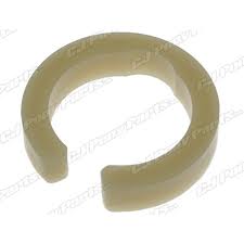
Steering Stop
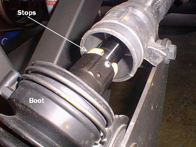
Boot clamp released, boot pulled back, steering stop snapped in place.
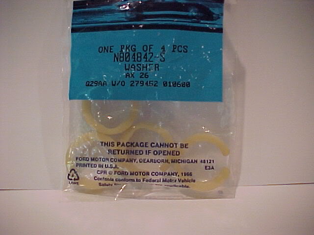
Took me (s2ki user SH99) a while to find these! Ford Part Numbers below. The measurement is the thickness of the stop--the thicker it is the more steering is limited. The correct size depends on the width and offset of your front wheels. Most of the Ford parts come in a bundle pack.
Ford Part # - Stop Thickness (pieces in pack)
N807853-S Steering Limiter - 2.4mm or 0.095inch (15pk)
W705003-S Steering Limiter - 4.25mm 0.167inch (4pk)
N804842-S Steering Limiter - 6.5mm 1/4inch (4pk)
W705004-S Steering Limiter - 7.25mm 0.285inch (4pk)
N808506-S Steering Limiter - 10.65mm 0.42inch (1pk)
Ford Bundle Pack of Steering Stops
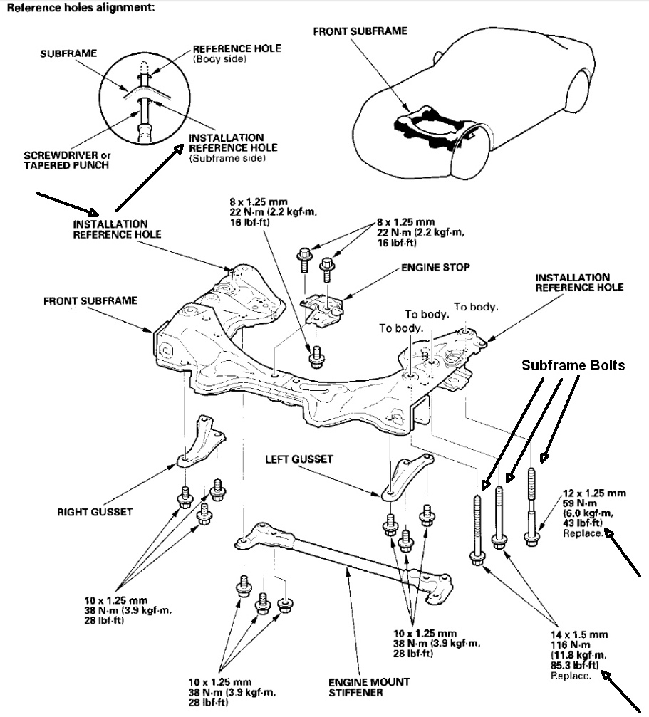
Check for Loose Subframe Bolts
It's pretty common for these bolts too loosen up over time. If loose the subframe can move around and change your alignment settings and cause strange handling quirks. My alignment settings began to drift around so I checked the subframe bolts and sure enough, eight of 12 bolts were loose. All 12 bolts are relatively easy to access--nothing has to be removed for access. The Workshop Manual says to replace the bolts when you loosen them but I just put a bunch of Locktite on the bolts and torqued them to about 10% over speq. I'll check them regularly for looseness.
Be sure and verify the alignment of the subframe using the subframe Installation Reference Holes (shown below) before tightening. Just insert a screwdriver or big round punch into the holes and feel for the same clearance on both sides. A big punch will be more accurate. Also note that some of the bolts are 17mm and some 19mm (socket size) and require different torque specs. The 19mm bolts can be difficult to reinstall so I suggest just torquing them and not removing them to add Locktite.
Front Subframe
Rear Subfarme

These are the alignment settings I use on my 2001 AP1 race car. I have adjustable ball joints in the front and a bump steer kit in the rear that allow lots of negative camber:
Front -3.5 degrees camber, 7 degrees caster, 0 toe
Rear -3.0 camber (the maximum I can get), 0.25 inch total toe-in. Some people recommend less toe-in for track S2000s (0.125 inch total) but 0.25 inch works well for me. I tried running less toe-in but the car's rear end was too twitchy.